
A 3 phase transformer should be sized for the way the load behaves on site, not only for the voltage conversion shown on a drawing. That is especially true when an Australian installation has to run imported machinery, integrate a plant upgrade, or support a mixed load made up of motors, drives, controls, and sensitive electronics.
For contractors, installers, and project teams, the usual questions are practical. Is the running load enough to choose the kVA rating? Will motor starting create a voltage dip? Does the project need isolation, or only voltage conversion? Will harmonics from drives increase transformer heating? These are the points that decide whether the selected unit runs reliably or becomes a problem after commissioning.
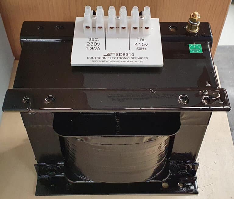
Southern Electronic Services supports these applications with Australian-made transformer solutions for industrial, commercial, mining, rail, renewable, and data centre projects, including imported equipment that does not match the local 415 V supply.
Key points
- 3 phase transformers are selected in kVA, not kW.
- Power factor affects the apparent power the transformer must carry.
- Transformer inrush and motor starting current are different checks.
- Harmonic-producing loads can increase losses and operating temperature.
- A complete load schedule usually prevents under-sizing and unnecessary oversizing.
Why transformer sizing starts with kVA
Transformers are rated in kVA because the windings carry total current, not only the useful output power consumed by the load. That is why kW on its own is not enough. If the equipment schedule gives kW, the power factor has to be considered before the transformer size can be judged properly.
The basic relationship is straightforward:
kVA = kW ÷ power factor
If a machine is rated at 30 kW with a power factor of 0.8, the running demand seen by the transformer is 37.5 kVA. That figure is the starting point for selection. It is not always the finished answer, because the running load may not capture start-up conditions, duty cycle, or waveform distortion.
A practical sizing example
Take an imported 3 phase machine that needs 220 V and has a connected load of 22 kW at 0.85 power factor. The running apparent power is:
22 ÷ 0.85 = 25.9 kVA
At first glance, a 30 kVA transformer may appear suitable. It may be suitable if the load is steady, mostly linear, and free from heavy motor starts. It may not be the right choice if the machine includes direct on line motors, a high cycling duty, or additional auxiliaries such as heaters, pumps, or control gear that were not included clearly on the original schedule.
That is where project knowledge matters. A transformer should be selected around the real duty of the installation, not only the nearest standard size above the calculated running load.
What should be on the load schedule
A good sizing decision depends on the information supplied at the start. Missing details usually lead to guesswork, and guesswork tends to produce either excess margin or a transformer that is too close to the limit.
Input
- Supply voltage and required output voltage
- Full load current, kW, or kVA
- Power factor
- Motor size and starting method
- Duty cycle
- Harmonic-producing equipment
- Site conditions and enclosure
- Isolation requirement
Why it matters
- Confirms the transformation ratio and whether the equipment suits the local network
- Establishes the base demand
- Converts kW into the kVA the transformer must carry
- Identifies possible voltage dip and short-term current demand
- Shows whether the load is steady, intermittent, or high cycling
- Helps assess added heating from drives, rectifiers, or UPS loads
- Affects cooling, protection, and practical installation
- Determines whether an isolation transformer is needed instead of a simpler conversion approach
For imported equipment, these details matter even more. Voltage conversion may be only part of the requirement. The project may also need electrical separation, a specific secondary arrangement, or compatibility with local protection and earthing practice. SES covers these applications through its range of 3 phase transformers.
![]()
Inrush and motor starting are different events
Two high-current conditions are often grouped together during specification, even though they come from different causes. Transformer inrush occurs when the transformer is energised and the magnetic core is first excited. Motor starting current occurs when the connected machine starts and draws a short-term surge from the supply.
Both can affect performance, but in different ways. Transformer inrush may influence upstream protective devices and nuisance tripping. Motor starting can create a voltage dip on the secondary, particularly where the supply is weak or several loads start close together. If the transformer feeds compressors, conveyors, pumps, or hydraulic systems, the starting method should be reviewed early. A direct on line start places a much heavier demand on the transformer than a soft starter or variable speed drive.
Harmonics and derating
Modern industrial loads are often non-linear. Variable speed drives, rectifiers, UPS systems, and other switched power electronics can introduce harmonic currents that add heat and place extra stress on the transformer. In practical terms, that means a transformer can appear adequate based on running kVA, but still operate hotter than expected once harmonic-producing loads are included.
This is why harmonic content should be reviewed during sizing, especially on sites with drives, controls, or other electronic equipment. Where the load includes a large non-linear component, the final selection may need to allow for derating, cooling, or a different winding design rather than relying on the running figure alone.
Common mistakes that affect the final selection
The first mistake is sizing from kW alone and leaving out the power factor. The second is assuming the running load tells the full story, even though the machine may have heavy starts or rapid cycling. The third is treating every project as a simple voltage conversion when the installation may also need isolation or a defined secondary arrangement. Harmonics are also missed regularly, especially on plants that use drives and other electronic power conversion.
In practice, most sizing issues come back to the same point. The transformer was chosen from incomplete project data.
What to send SES for sizing support
The most useful starting point is a load schedule plus the equipment nameplate details. Include the supply voltage, required output voltage, full load current, power factor if known, motor data, starting method, duty cycle, ambient conditions, and any known harmonic-producing loads. That allows the transformer to be sized around the real operating duty rather than a simplified assumption.
For imported machinery, plant upgrades, or projects where power quality matters, send those details through the SES contact page. That makes it easier to confirm whether a standard transformer is suitable or whether a custom-built unit is the better fit.
FAQ
1. How do I calculate transformer kVA for a 3 phase load?
Use the machine current and voltage, or divide the load kW by the power factor. The result is the apparent power the transformer must carry during normal operation.
2. Why can the calculated running kVA still be too low?
Because the running figure may not include motor starting current, intermittent overloads, ambient conditions, or harmonic-related heating. Those factors can change the final selection.
3. Does every motor load need extra transformer capacity?
No. The answer depends on motor size, starting method, supply stiffness, and how often the load starts. Some applications need very little margin, while others need a more detailed review.
4. When do harmonics become important in transformer sizing?
They become important when the load includes a meaningful share of drives, rectifiers, UPS equipment, or other electronic power conversion. In those cases, added losses can increase operating temperature.
5. Should I choose an isolation transformer or an autotransformer?
Choose an isolation transformer where the project needs separation between primary and secondary, improved noise control, or a specific secondary arrangement. An autotransformer may suit straightforward voltage conversion where those features are not required.
Get the Latest in Power Transformer Solutions
Get industry insights, product updates, and exclusive offers


